Makita LS1220 Spécifications
Naviguer en ligne ou télécharger Spécifications pour Scies à onglets Makita LS1220. Makita LS1220 Specifications Manuel d'utilisatio
- Page / 32
- Table des matières
- MARQUE LIVRES
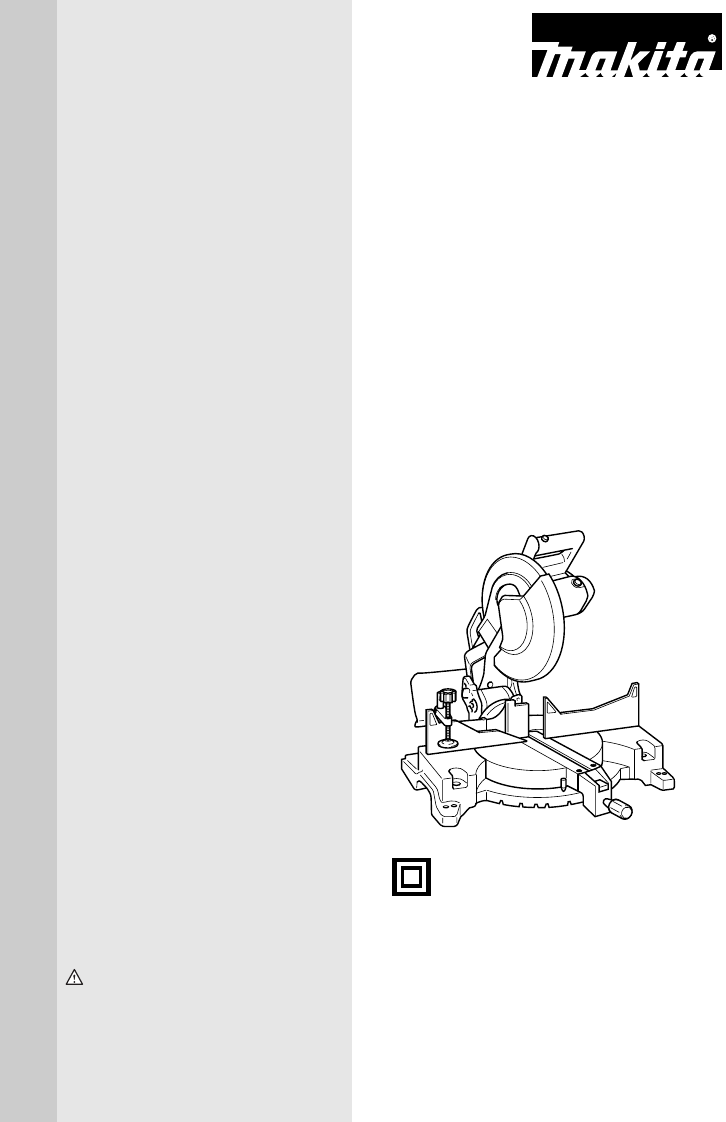
- Compound Miter Saw 1
- SPECIFICATIONS 2
- Before Operating Tool 2
- Save it for future reference 2
- GENERAL SAFETY PRECAUTIONS 2
- ADDITIONAL SAFETY RULES 4
- SAVE THESE INSTRUCTIONS 6
- INSTALLATION 7
- FUNCTIONAL 7
- DESCRIPTION 7
- Positioning kerf board 8
- Adjusting the miter angle 9
- Adjusting the bevel angle 10
- Switch action 10
- ASSEMBLY 11
- Dust bag 13
- Securing workpiece 13
- Sub-fence 13
- Vertical vise 14
- OPERATION 15
- Bevel angle 17
- Miter angle 17
- Left and Right 0 - 45˚ 17
- Table (A) 18
- Table (B) 18
- Table (C) 22
- 1. Set plate 23
- 2. Holder 23
- 3. Screw 23
- MAINTENANCE 24
- Replacing carbon brushes 26
- ACCESSORIES 27
- Makita Canada Inc 29
- 1950 Forbes Street 29
- Whitby, Ontario 29
- Certificate of Warranty 30
- Mail to Makita 30
- Factory Service Centres 31
- Makita Corporation of America 32
Résumé du contenu
INSTRUCTION MANUALWARNING:For your personal safety, READ and UNDERSTAND before using.SAVE THESE INSTRUCTIONS FOR FUTURE REFERENCE.Compound Miter SawEq
10Adjusting the bevel angleTo adjust the bevel angle, loosen the lever at the rear of thetool counterclockwise.Push the handle to the left to tilt the
11NEVER use the tool if it runs when you simply pull theswitch trigger without pressing the lock-off button.Return tool to a Makita service center for
12To remove the blade, use the socket wrench to loosen thehex bolt holding the center cover by turning it counterclock-wise. Raise the blade guard and
13Dust bagThe use of the dust bag makes cutting operations clean anddust collection easy. To attach the dust bag, fit it onto thedust nozzle.When the
14CAUTION:• When performing left bevel cuts, flip the fence over to theleft position as shown in the figure. Otherwise, it willcontact the blade or a
15CAUTION:• Always rotate the vise nut to the right fully when securingthe workpiece. Failure to do so may result in insufficientsecuring of the workp
16• Gently press down the handle to perform the cut. If thehandle is pressed down with force or if lateral force isapplied, the blade will vibrate and
17• When pressing the handle down, apply pressure parallelto the blade. If the pressure is not parallel to the bladeduring a cut, the angle of the bla
18There are crown and cove molding joints which aremade to fit “Inside” 90° corners ((1) and (2) in Fig. A) and“Outside” 90° corners ((3) and (4) in F
19Example:In the case of cutting 52/38° type crown molding forposition (1) in Fig. A:• Tilt and secure bevel angle setting to 33.9°LEFT.• Adjust and s
2SPECIFICATIONSBlade diameter ... 305 mm (12”)Hole diamete
20EN0002-1Compound Miter Saw Miter and Bevel Angle Settings00003152˚38˚CeilingWallWall to Crown Molding Angle: 52/38 degreesWall Angle (deg.)Bevel Ang
21 EN0003-1Compound Miter Saw Miter and Bevel Angle Settings00003245˚45˚CeilingWallWall to Crown Molding Angle: 45 degreesWall Angle (deg.)Bevel Angle
22Crown molding stoppers (optional accessories) alloweasier cuts of crown molding without tilting the sawblade. Install them on the base as shown in t
23CAUTION:• Use straight wood of even thickness as the wood facing.• Use screws to attach the wood facing to the guide fence.The screws should be inst
24Carrying toolMake sure that the tool is unplugged. Secure the blade at 0°bevel angle and the turn base at right miter angle fully. Lowerthe handle f
25Lower the handle fully and lock it in the lowered positionby pushing in the stopper pin. Square the side of theblade with the face of the guide fenc
26Make sure that the pointer on the turn base point to0° on the bevel scale on the arm. If it does not pointto 0°, loosen the screw which secures the
27After use• After use, wipe off chips and dust adhering to the toolwith a cloth or the like. Keep the blade guard cleanaccording to the directions in
Memo28
29FoldCutStampTimbreMakita Canada Inc.1950 Forbes Street,Whitby, OntarioL1N 7B7
34.KEEP WORK AREA CLEAN. Clutteredareas and benches invite accidents.5.DON’T USE IN DANGEROUS ENVIRON-MENT. Don’t use power tools in damp orwet locati
30Your answers to the following questions are appreciated.Date Purchased Model No.Serial No.Initial Last NameStreet AddressCity ProvinceAGE:Male Femal
31Factory Service CentresFor the authorized service centre nearest you please refer to the local yellow pages directory under “tools” or con-tact our
Warranty PolicyEvery Makita tool is thoroughly inspected and tested before leaving the factory. It is warranted to be free of defects fromworkmanship
4VOLTAGE WARNING: Before connecting the tool to a power source (receptacle, outlet,etc.) be sure the voltage supplied is the same as that specified on
510.Check the blade carefully for cracks ordamage before operation. Replacecracked or damaged blade immediately.Gum and wood pitch hardened on bladess
6SAVE THESE INSTRUCTIONSWARNING:MISUSE or failure to follow the safety rules stated in thisinstruction manual may cause serious personal injury.
7INSTALLATIONBench mountingWhen the tool is shipped, the handle is locked in the loweredposition by the stopper pin. Release the stopper pin by lower-
8If the see-through blade guard becomes dirty, or sawdustadheres to it in such a way that the blade is no longer easilyvisible, unplug the saw and cle
9Maintaining maximum cutting capacityThis tool is factory adjusted to provide the maximum cuttingcapacity for a 305 mm (12”) saw blade.When installing
Plus de documents pour Scies à onglets Makita LS1220

Produits connexes et manuels pour Scies à onglets Makita LS1220


 (136 pages)
 (36 pages)
(16 pages)
(36 pages)
(36 pages)
(16 pages)

 (112 pages)
 (76 pages)
© 2020, manymanuals.fr. Tous droits réservés | 0.160 s |
 Manymanuals.com
 Manymanuals.de
 Manymanuals.fr
 Manymanuals.it
 Manymanuals.pl
 Manymanuals.cz
 Manymanuals.es
 Manymanuals-pt.com
Commentaires sur ces manuels